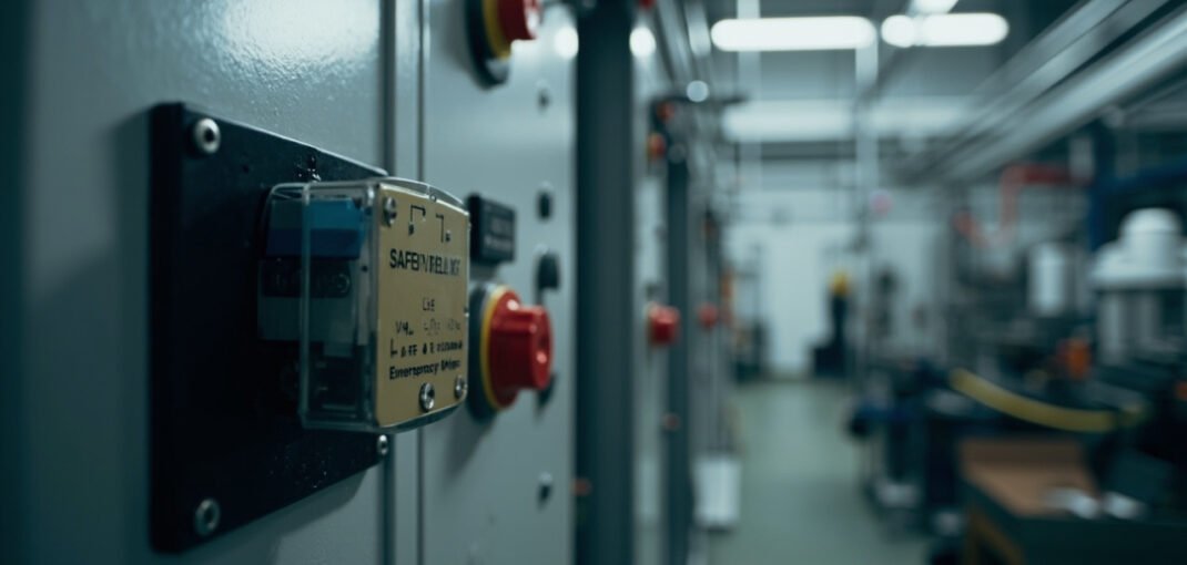
# Safety Relay Configuration: Category 3/4 Circuits, E-Stop Wiring, and Diagnostic Coverage
Safety relays are crucial components in industrial automation systems, ensuring that machinery operates safely and efficiently while protecting operators and equipment from harm. Proper configuration of safety relays, especially in accordance with international standards like ISO 13849 and IEC 62061, is essential for achieving the desired safety performance levels. This article delves into the intricacies of safety relay configuration, focusing on safety categories, relay architecture, emergency stop (E-Stop) wiring, dual-channel input wiring, diagnostic coverage, safety interlock switches, and reset procedures. We will also explore some of the leading safety relay products available on the market today.
1. Safety Categories and Performance Levels
1.1 Safety Categories per ISO 13849-1
ISO 13849-1 defines five safety categories (B, 1, 2, 3, and 4) that describe the architecture and reliability of safety-related control systems. The categories are as follows:
- Category B: Basic safety principles are applied. No redundancy or diagnostics are required.
- Category 1: Well-tried safety principles are applied. Single-channel architecture with high reliability components.
- Category 2: Single-channel architecture with periodic testing. Includes diagnostic coverage.
- Category 3: Single-fault tolerant architecture. Redundancy is used to detect faults.
- Category 4: Multiple-fault tolerant architecture. Redundancy and continuous diagnostics are employed.
1.2 Performance Levels (PL)
Performance Levels (PL) range from PL a (lowest) to PL e (highest) and indicate the ability of a safety function to perform as intended. The higher the PL, the lower the probability of dangerous failure.
| Category | PL Range | Description |
|---|---|---|
| B | PL a | Basic safety principles |
| 1 | PL b | Well-tried components and principles |
| 2 | PL c | Periodic testing, diagnostic coverage |
| 3 | PL d | Single-fault tolerant, redundancy |
| 4 | PL e | Multiple-fault tolerant, continuous diagnostics |
1.3 Achieving Higher Performance Levels
To achieve higher performance levels, such as PL d or PL e, safety relays must incorporate advanced features like dual-channel input monitoring, cross-fault detection, and forced-guided relay contacts. For instance, the Schneider Sepam S40 protection relay is designed to meet these stringent requirements, offering robust protection and diagnostic capabilities.
2. Safety Relay Architecture
2.1 Dual-Channel Input Monitoring
Dual-channel input monitoring is a fundamental aspect of safety relay design. It involves monitoring two independent input signals to ensure that both channels agree before allowing the machine to operate. This redundancy helps detect faults and prevents unsafe conditions.
2.2 Cross-Fault Detection
Cross-fault detection is a feature that checks for faults between the two channels. If a fault is detected, the safety relay will initiate a shutdown. This is crucial for maintaining the integrity of the safety function.
2.3 Forced-Guided Relay Contacts
Forced-guided relay contacts ensure that the relay contacts are in the correct position. If a contact fails to move as intended, the safety relay will detect the discrepancy and trigger a shutdown. This feature is essential for achieving high diagnostic coverage.
Example Product
The Omron V680-HAM42-DRT magnetic safety switch is an excellent example of a safety relay with dual-channel input monitoring and forced-guided contacts, making it suitable for applications requiring high safety integrity.
3. E-Stop Wiring Topology
3.1 Category 0 (Immediate Stop)
Category 0 E-Stops provide an immediate shutdown of the machine by removing power from the actuators. This is the most basic form of emergency stop and is typically used in situations where a quick shutdown is necessary.
3.2 Category 1 (Controlled Stop then Power Removal)
Category 1 E-Stops involve a controlled stop of the machine before power is removed. This allows for a more graceful shutdown, which can be beneficial in applications where an immediate power cut could cause additional hazards or damage.
Wiring Considerations
When configuring E-Stops, it is important to ensure that the wiring is done in accordance with the selected category. For instance, Category 0 E-Stops require a direct and uninterrupted path to the actuator, while Category 1 E-Stops may involve additional control circuitry to facilitate the controlled stop.
4. Dual-Channel Input Wiring
4.1 Series vs. Parallel Connection
Dual-channel input wiring can be configured in either a series or parallel configuration:
- Series Connection: Both channels must be closed for the safety relay to allow the machine to operate. This configuration is simple but can lead to nuisance trips if one channel fails open.
- Parallel Connection: Either channel can be closed to allow the machine to operate. This configuration is more fault-tolerant but requires additional logic to ensure safety.
4.2 Test Pulse Generation
Test pulse generation involves sending periodic test pulses to the safety relay to verify the integrity of the input channels. This is particularly important in Category 2 and 3 systems, where periodic testing is required.
Example Product
The BERNSTEIN SLC-F-024-20/20-R4 guard locking safety interlock switch is designed for applications requiring dual-channel input wiring with test pulse generation, ensuring high reliability and safety.
5. Diagnostic Coverage (DC)
5.1 Levels of Diagnostic Coverage
Diagnostic Coverage (DC) is a measure of the effectiveness of diagnostic tests in detecting faults. The levels of DC are:
- None: No diagnostics.
- Low: 60% DC.
- Medium: 90% DC.
- High: 99% DC.
5.2 Calculating DC for a Safety Function
The DC for a safety function can be calculated using the following formula:
\[ \text{DC} = \frac{\text{Number of Detectable Faults}}{\text{Total Number of Faults}} \times 100\% \]
For example, if a safety function has 100 possible faults and 90 of them are detectable, the DC would be 90%.
Example Product
The Schmersal AZ/AZM 200-B30-LTAG1P1 safety interlock switch offers high diagnostic coverage, making it suitable for applications requiring high safety integrity.
6. Safety Interlock Switches
6.1 Coded Magnetic Switches
Coded magnetic switches use magnetic fields to detect the position of a guard or door. They are highly reliable and resistant to tampering.
6.2 Guard Locking Devices
Guard locking devices physically prevent access to hazardous areas until the machine is in a safe state. They are commonly used in high-risk applications.
6.3 Hinge Switches
Hinge switches are integrated into the hinges of doors or guards and are activated when the door is opened or closed. They provide a simple yet effective means of monitoring access.
Example Product
The Leuze RSL420-XL safety laser scanner is an advanced safety interlock device that uses laser technology to detect obstacles and ensure safe operation.
7. Reset and Start-Up Procedures
7.1 Monitored Start
A monitored start involves verifying that all safety conditions are met before allowing the machine to start. This is typically done through a combination of input signals and diagnostic checks.
7.2 Manual Reset
Manual reset requires an operator to manually reset the safety relay after a shutdown. This ensures that the operator is aware of the reason for the shutdown and takes appropriate action.
7.3 Automatic Reset
Automatic reset automatically resets the safety relay after a shutdown once all safety conditions are met. This is less common and is typically used in low-risk applications.
Example Product
The Omron MY4N-J general purpose relay can be used in conjunction with safety relays to provide monitored start and manual reset functionality.
8. Common Safety Relay Modules
8.1 Pilz PNOZ
The Pilz PNOZ series is a widely used range of safety relays that offer a variety of configurations to meet different safety requirements. They are known for their reliability and ease of use.
8.2 Schneider Harmony XSZ
The Schneider Harmony XSZ series provides robust safety relay solutions with advanced diagnostic features. They are designed for use in demanding industrial environments.
8.3 Siemens 3SK1
The Siemens 3SK1 series offers versatile safety relay modules with high diagnostic coverage and flexible configuration options. They are suitable for a wide range of applications.
8.4 Omron G9SA
The Omron G9SA series is a compact and cost-effective safety relay solution that provides reliable protection for machinery and operators.
FAQ
Q1: What is the difference between Category 3 and Category 4 safety relays?
Category 3 relays are single-fault tolerant, while Category 4 relays are multiple-fault tolerant. This means that Category 4 relays can tolerate more faults before failing to a safe state.
Q2: How do I determine the appropriate safety category for my application?
The appropriate safety category depends on the risk assessment of the machinery and the desired performance level. A higher risk requires a higher category.
Q3: What is the role of diagnostic coverage in safety relay configuration?
Diagnostic coverage ensures that faults are detected and that the safety relay can respond appropriately. Higher diagnostic coverage means better fault detection and higher safety integrity.
Q4: Can I use a general-purpose relay for safety applications?
No, general-purpose relays do not provide the necessary safety features and diagnostic capabilities required for safety applications. Always use certified safety relays.
Q5: How often should safety relays be tested?
Safety relays should be tested regularly, with the frequency depending on the application and the manufacturer’s recommendations. Periodic testing ensures that the relay is functioning correctly and that the safety function is maintained.
Conclusion
Proper configuration of safety relays is vital for ensuring the safety of industrial machinery and operators. By understanding the safety categories, relay architecture, E-Stop wiring, dual-channel input wiring, diagnostic coverage, and reset procedures, engineers can design and implement effective safety systems. The products mentioned, such as the Schneider Sepam S40 protection relay, Omron V680-HAM42-DRT magnetic safety switch, and BERNSTEIN SLC-F-024-20/20-R4 guard locking safety interlock switch, offer robust solutions for various safety requirements. For more information on these and other safety relay products, please browse our selection.
Call to Action
Explore our range of safety relay modules and related products to find the perfect solution for your industrial automation needs. Click the links below to learn more: