
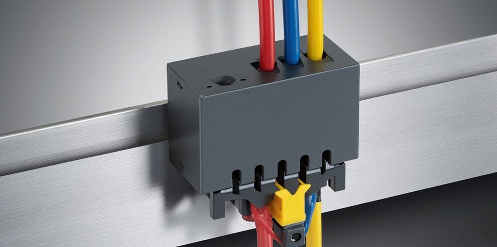
Safety relay configuration is a critical process in industrial automation that ensures machinery operates within safe parameters, protecting both personnel and equipment. A safety relay acts as an intelligent switching device that monitors safety circuits, such as emergency stops, safety gates, light curtains, and interlock switches. When properly configured, it can detect faults, trigger shutdowns, and maintain compliance with international safety standards like ISO 13849-1 and IEC 62061. This comprehensive guide explores everything you need to know about configuring safety relays effectively, from understanding basic architecture to advanced parameterization techniques used in modern manufacturing environments.
What Is a Safety Relay and Why Configuration Matters
A safety relay is a specialized electromechanical or solid-state device designed to implement safety functions in industrial systems. Unlike standard relays, safety relays feature redundant internal circuits, force-guided contacts, and self-monitoring capabilities that ensure any internal failure is detected and causes the system to enter a safe state. Configuration refers to the process of selecting input devices, defining logic operations, setting response times, and establishing output behaviors that align with the required Performance Level (PL) or Safety Integrity Level (SIL).
Proper configuration is not optional. Incorrectly set parameters can result in dangerous machine behavior, regulatory non-compliance, increased liability, and potential injury. Configuration decisions directly influence the category of the safety function, its diagnostic coverage (DC), and the Mean Time To Dangerous Failure (MTTFd) values that determine the overall safety rating.
Core Components of a Safety Relay System
Before configuration begins, it is essential to understand the structural elements that form a complete safety relay system. The following table outlines the primary components and their roles:
| Component | Function | Configuration Considerations |
|---|---|---|
| Input Devices | E-stops, light curtains, interlock switches | Select single or dual-channel input modes |
| Logic Unit | Processes input signals and applies logic | Define AND/OR conditions and time delays |
| Output Contacts | Switches the safety-related load | Choose normally open/closed, instantaneous or delayed |
| Feedback Loop | Monitors contactors or expansion modules | Enable EDM (External Device Monitoring) when required |
| Reset Mechanism | Manual or automatic restart | Configure monitored or non-monitored reset |
Step-by-Step Safety Relay Configuration Process
Configuring a safety relay involves several methodical steps. Following a structured workflow minimizes errors and ensures the resulting safety function meets the required risk reduction level.
Step 1: Conduct a Risk Assessment
Before any wiring or parameterization, perform a thorough risk assessment per ISO 12100. Identify hazards, estimate severity, frequency of exposure, and possibility of avoidance. This assessment determines the required Performance Level (PL a through PL e) or SIL (1 through 3) that the safety relay must achieve.
Step 2: Select the Appropriate Safety Relay
Choose a safety relay that supports the necessary input devices, has sufficient output contacts, and is rated for the calculated PL/SIL. Leading manufacturers such as Pilz, Siemens, SICK, Allen-Bradley, and Omron offer product families with different voltage ratings, response times, and expansion capabilities.
Step 3: Wire the Input Channels
Connect safety devices using either single-channel or dual-channel wiring. Dual-channel configurations offer higher diagnostic coverage and are typically required for PL d and PL e applications. The wiring method chosen directly impacts the achievable safety category.
Step 4: Configure the Logic and Timing Parameters
Modern configurable safety relays use DIP switches, rotary selectors, or PC-based software to set operating modes. Common parameters include:
- Cross-fault monitoring: Detects shorts between input channels.
- Synchronization time: Maximum allowable delay between channel signals.
- Reset mode: Manual monitored reset, automatic reset, or anti-restart.
- Time delay: For stop category 1 controlled stops (typically 0.1s to 30s).
- Output logic: AND/OR combinations when using expansion modules.
Step 5: Implement Feedback and EDM
External Device Monitoring (EDM) verifies that downstream contactors or motor starters have actually dropped out before allowing a restart. Connect normally closed contacts of the contactors to the designated EDM terminals to complete this critical monitoring loop.
Step 6: Validate and Document the Configuration
After configuration, perform a full functional test. Simulate every safety event, verify response times, and check that reset functions work as expected. Document all parameter settings, wiring diagrams, and test results for compliance audits.
Common Safety Relay Terminal Designations
Understanding terminal naming conventions speeds up installation and reduces wiring errors. While manufacturers use slightly different labels, the underlying principles remain consistent.
| Terminal Code | Typical Purpose | Notes |
|---|---|---|
| S11 / S12 | Power supply inputs | 24 VDC or 230 VAC depending on model |
| S21 / S22 | Channel 1 input | Connect to safety device contact A |
| S31 / S32 | Channel 2 input | Connect to safety device contact B |
| 13/14, 23/24, 33/34 | Safety output contacts (NO) | Switch the load when safe |
| 41/42 | Auxiliary output (NC) | Signaling or EDM loop |
| Y1/Y2 | Reset input | Connect reset pushbutton for manual restart |
Software-Based Configuration vs. Hardware DIP Switches
Two primary configuration methods exist in the industry. Traditional safety relays use DIP switches and rotary dials for parameter selection, which is fast and requires no additional tools. However, this approach limits complexity and offers no detailed diagnostics.
Software-configured safety relays, such as the Pilz PNOZmulti 2, Siemens Sirius 3SK2, or SICK Flexi Soft, connect to a PC via USB or Ethernet. Engineers use graphical programming environments to define logic blocks, set time delays, and create complex safety functions. Benefits include:
- Centralized configuration of multiple safety zones from one project file.
- Real-time diagnostics and event logging for predictive maintenance.
Categories
-

Contactor Failure Modes: Coils, Chatter, Welded Poles
September 30, 2026 -

Cogging Torque Definition: What It Is and How It Affects Motor Performance
September 28, 2026 -

Status Prediction Analysis: Methods, Models, and Applications
September 26, 2026 -

-

Motor Starter Selection: DOL, Star-Delta, Soft, VFD
September 24, 2026