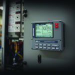
ABB Power Factor Correction Controller Configuration: RVC-L-12 Step Controller, Capacitor Bank Switching, Target Power Factor Setting, Reactive Power Compensation, Harmonic Distortion Mitigation
Introduction
In industrial electrical systems, maintaining an optimal power factor is crucial for both operational efficiency and cost management. Power factor (PF) is the ratio of real power (kW) to apparent power (kVA) in an AC circuit, and it indicates how effectively electrical power is being converted into useful work output. A low power factor can lead to increased energy losses, reduced system capacity, and higher electricity costs due to penalties imposed by utility companies for excessive reactive power consumption (kVAR).
To address these issues, power factor correction (PFC) systems are employed to compensate for reactive power, thereby improving the power factor and reducing energy costs. The ABB RVC-L-12 12-step power factor controller is a sophisticated device designed to automate the process of power factor correction in industrial and commercial facilities. This article provides a comprehensive guide to configuring the ABB RVC-L-12 controller, including setting the target power factor, managing capacitor bank switching, and mitigating harmonic distortion. For detailed product specifications and purchasing information, refer to the ABB RVC-L-12 Power Factor Controller.
Power Factor Target Setting and Reactive Power Calculation
Target Power Factor Selection
The target power factor is a critical parameter that determines the effectiveness of the PFC system. Common target power factors are 0.95, 0.98, and unity (1.0).
- 0.95: A target power factor of 0.95 is often recommended as it provides a good balance between the benefits of power factor correction and the cost of additional equipment. This setting is widely used in industrial applications.
- 0.98: A target power factor of 0.98 offers higher efficiency and lower energy costs but requires more sophisticated equipment and precise tuning.
- Unity (1.0): Achieving a unity power factor is theoretically ideal but often impractical due to the increased cost and complexity of the PFC system.
To set the target power factor on the ABB RVC-L-12 controller, navigate to the parameter settings and adjust the target PF value. This can be done via the controller’s user interface or through a connected software platform.
Reactive Power Compensation Calculation
The amount of reactive power compensation required (kVAR) can be calculated using the formula:
\[ \text{Required kVAR} = \text{Active Power (kW)} \times (\tan \phi_1 – \tan \phi_2) \]
Where:
- \(\phi_1\) is the phase angle corresponding to the existing power factor.
- \(\phi_2\) is the phase angle corresponding to the target power factor.
The ABB RVC-L-12 controller, specifically the model 2TAZ460104R1120, provides 12 output steps for capacitor bank switching. The step size can be configured as equal or unequal, with the first step typically set for minimum compensation to ensure fine control.
Capacitor Bank Disconnect
For safety and maintenance, a motor isolation switch such as the ABB OS400D13N2 is recommended. This switch allows for the disconnection of the capacitor bank from the power supply during maintenance or in case of a fault.
Capacitor Bank Switching Sequence and Controller Output
Switching Sequence
The ABB RVC-L-12 controller supports two main switching sequences:
- Circulating Switching: This method rotates through the capacitor steps, ensuring even wear and prolonging the life of the capacitors. It is particularly useful in applications where the load is variable and frequent switching is required.
- Classic Switching: This method switches the capacitors in a fixed sequence, which is simpler but may lead to uneven wear.
The controller’s 12 output relays correspond to the 12 capacitor steps, allowing for precise control over the switching process. For optimal performance, contactors from the ABB CL series with pre-insertion resistors are recommended. These resistors help to reduce inrush currents and extend the life of the capacitors.
Switching Delay and Timing
The switching delay between steps can be set between 10 to 60 seconds using the ABB TP40IA time delay relay. This delay is crucial to prevent rapid switching, which can lead to system instability and increased harmonic distortion. The ABB TP40IA time delay relay can also be used for auxiliary functions, such as initiating alarms or triggering other control sequences.
Capacitor Step Priority and Rotation
The controller employs an algorithm that prioritizes capacitor steps based on usage, ensuring equal wear and extending the life of the capacitor bank. This rotation algorithm can be configured to operate in manual or automatic mode, providing flexibility in managing the PFC system.
Voltage and Current Sensor Configuration
Voltage Transformer (VT) and Current Transformer (CT) Selection
The ABB RVC-L-12 controller supports direct connection for voltage inputs of 400V, 415V, and 480V. The current transformer (CT) ratio should be selected based on the main incoming current of the system. The controller’s CT ratio parameter setting allows for adjustments to accommodate different system configurations.
Phase Connection and Polarity
The controller supports 3-phase 4-wire systems, with phase connections labeled as L1, L2, and L3. Proper polarity marking (P1, P2, S1, S2) is essential for accurate power factor measurement. The wiring direction must be carefully observed to ensure correct operation.
Power Factor Measurement
The ABB PFEA112-65 tension controller can be used for comparison in industrial measurement applications. This device offers advanced features for power factor measurement and can be integrated with the RVC-L-12 controller for comprehensive system monitoring.
Harmonic Distortion and Detuned Reactor
Total Harmonic Distortion (THD) Impact
Harmonic distortion can cause significant issues in PFC systems, including capacitor overload and system instability. The ABB RVC-L-12 controller includes a harmonic alarm threshold setting to alert operators when THD levels exceed safe limits.
Resonance Frequency and Detuned Reactor
The resonance frequency between the capacitor and transformer inductance can be calculated to determine the appropriate detuned reactor. Detuned reactors with 7% or 14% impedance are commonly used for harmonic filtering. These reactors help to mitigate the effects of harmonic distortion and protect the capacitor bank from overload.
Harmonic Protection
The controller’s harmonic alarm threshold can be configured per IEC 60831 standards to provide protection against capacitor overload. For more advanced harmonic filtering, an active harmonic filter can be used in conjunction with the detuned reactor. The ABB PLUTO B46 v2 safety controller can be employed for capacitor bank safety interlock, providing an additional layer of protection.
Comparison Table: PFC Controller Features
| Feature | ABB RVC-L-12 | Competitor A | Competitor B | Competitor C |
|---|---|---|---|---|
| Number of Steps | 12 | 10 | 8 | 12 |
| Target PF Range | 0.90 – 0.99 | 0.85 – 0.98 | 0.90 – 0.98 | 0.90 – 0.99 |
| CT Ratio Range | 50:5 – 5000:5 | 50:5 – 4000:5 | 50:5 – 5000:5 | 50:5 – 5000:5 |
| Harmonic Alarm Function | Yes | No | Yes | Yes |
| Detuned Reactor Support | Yes | No | Yes | Yes |
| Switching Sequence | Circulating | Classic | Circulating | Circulating |
| Time Delay Setting | 10-60s | 10-50s | 10-60s | 10-60s |
FAQ
1. How do I set the target power factor on the ABB RVC-L-12 controller?
The target power factor can be set via the controller’s user interface or through a connected software platform. Navigate to the parameter settings and adjust the target PF value to the desired level.
2. What is the recommended switching delay between steps?
The recommended switching delay is between 10 to 60 seconds. This delay can be configured using the ABB TP40IA time delay relay to prevent rapid switching and reduce harmonic distortion.
3. How does the ABB RVC-L-12 controller handle harmonic distortion?
The controller includes a harmonic alarm threshold setting to alert operators when THD levels exceed safe limits. Additionally, detuned reactors can be used for harmonic filtering, and the controller supports the integration of active harmonic filters for advanced harmonic mitigation.
Conclusion
Configuring the ABB RVC-L-12 power factor controller involves several key steps, including setting the target power factor, managing capacitor bank switching, and mitigating harmonic distortion. By carefully configuring these parameters, facility managers and electrical engineers can optimize the performance of their PFC systems, reduce energy costs, and enhance system reliability.
For more detailed information on the ABB RVC-L-12 controller and related products, visit the ABB RVC-L-12 Power Factor Controller product page.
—
Call to Action: For further assistance with configuring your power factor correction system, contact our technical support team or consult with a qualified electrical engineer. Explore our range of PFC products and solutions at Lisen Industry.