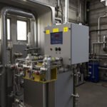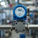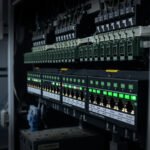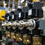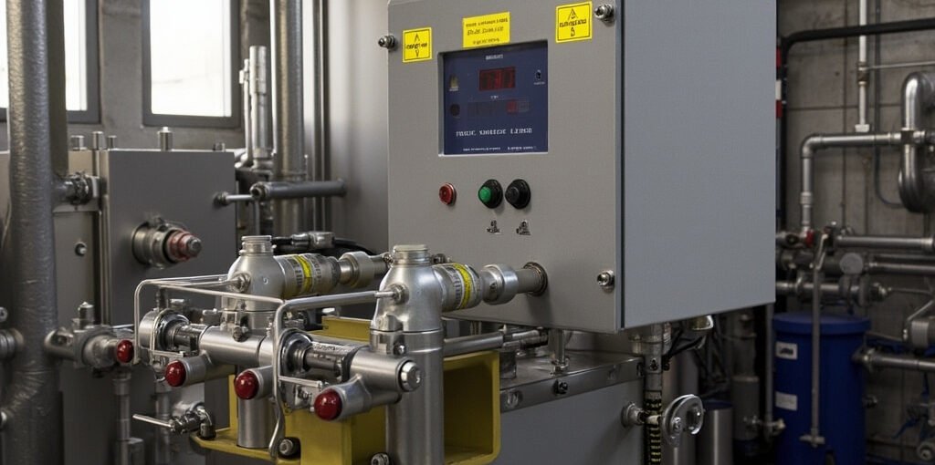
Honeywell Burner Safety System Configuration: Flame Safeguard Sequencing, Gas Valve Train Leakage Test, UV Scanner Sensitivity, BCU Interlock Wiring
Introduction
Industrial furnaces, boilers, ovens, and process heaters are critical equipment in manufacturing plants, where the combustion process must be carefully controlled to ensure both operational efficiency and safety. Burner management systems (BMS) play a crucial role in safeguarding personnel and equipment by controlling the ignition, operation, and shutdown of burners. The National Fire Protection Association (NFPA) 86 and European Standard (EN) 746 set stringent requirements for the design and operation of these systems to prevent explosions, fires, and other hazardous incidents.
Honeywell, a leader in industrial automation, offers a comprehensive range of flame safeguard controllers designed to meet these rigorous safety standards. The Honeywell RM7840L1018 Burner Controller, for instance, is a widely used model that provides advanced flame monitoring and burner control capabilities. Proper configuration of these systems is paramount to ensure they function as intended, protecting both personnel and equipment from potential hazards.
This article delves into the critical aspects of configuring Honeywell burner safety systems, focusing on flame safeguard sequencing, gas valve train leakage testing, UV scanner sensitivity and positioning, and burner control unit (BCU) interlock wiring. Understanding these elements is essential for combustion engineers and safety system technicians responsible for the reliable and safe operation of industrial combustion equipment.
Flame Safeguard Controller Sequencing
The flame safeguard controller is the heart of the BMS, orchestrating the sequence of operations that ensure safe and reliable burner operation. The Honeywell RM7840L1018 Burner Controller, available at Honeywell RM7840L1018 Burner Controller, provides a comprehensive set of sequencing functions:
Pre-purge Timing
Before ignition, the combustion chamber must be purged of any residual fuel or combustible gases. The pre-purge timing ensures that sufficient airflow is maintained for a specified duration to clear the chamber. This is typically set according to the volume of the combustion space and the airflow rate.
Pilot Valve Opening and Ignition Trial
Once the pre-purge cycle is complete, the pilot valve opens, allowing fuel to flow to the pilot burner. The ignition trial period begins, during which the ignition source is energized. The controller monitors for flame establishment within a defined timeframe.
Main Valve Opening and Flame Establishment
Upon successful ignition of the pilot flame, the main fuel valve opens, introducing fuel to the main burner. The controller verifies the establishment of the main flame within a specified flame establishment time. This step is crucial to ensure that the main burner ignites safely.
Flame Failure Response Time
The controller continuously monitors the flame signal. If the flame is lost during operation, the controller must respond within a specific flame failure response time to shut off the fuel supply and initiate a lockout condition. This rapid response is vital to prevent the accumulation of unburned fuel.
Post-purge Timing and Lockout on Flame Failure
After a flame failure, the system initiates a post-purge cycle to clear the combustion chamber of any residual fuel. The controller then enters a lockout state, requiring a manual reset before restarting the burner. This prevents unintended re-ignition and alerts operators to the fault condition.
Program Sequence Timing Adjustment
The Honeywell RM7840L1018 allows for precise adjustment of each timing parameter to accommodate the specific requirements of different combustion systems. This flexibility ensures optimal performance and safety across a wide range of applications.
Gas Valve Train Leakage Test Procedure
Ensuring the integrity of the gas valve train is critical to preventing gas leaks that could lead to hazardous situations. The Honeywell VE4040B1143 Gas Valve, available at Honeywell VE4040B1143 Gas Valve, is designed for reliable operation, but regular leakage testing is essential.
Manual Test Valve Isolation
Before conducting a leakage test, the gas supply must be isolated using the manual test valve. This prevents gas from entering the system during the test.
Automatic Leakage Test System
Modern BMS often include automatic leakage testing systems that can perform the test without manual intervention. These systems use pressure sensors to monitor for leaks and can alert operators if a leak is detected.
Test Pressure Requirement and Allowable Leakage Rate
The test is typically performed at a pressure slightly higher than the operating pressure to ensure the valve can hold pressure. The allowable leakage rate is defined by safety standards and must be within the specified limits.
Test Duration and Double Block and Bleed Configuration
The duration of the test depends on the system size and the test pressure. A double block and bleed configuration, where two valves isolate the gas supply and a bleed valve releases any trapped gas, provides an additional layer of safety.
Proof of Closure Test and Test Result Documentation
After the leakage test, a proof of closure test verifies that the valves have closed completely. All test results must be documented for compliance and maintenance tracking.
UV Flame Scanner Sensitivity and Positioning
The UV flame scanner is a critical component for detecting the presence of a flame. The Honeywell C7027A1056 Flame Detector, available at Honeywell C7027A1056 Flame Detector, offers high sensitivity and reliability.
UV Scanner Tube Type and Flame Rod vs UV Scanner
UV scanners use a photocell that is sensitive to ultraviolet radiation emitted by the flame. Flame rods, on the other hand, detect the presence of a flame by sensing the electrical conductivity of the ionized gases in the flame. UV scanners are generally preferred for their faster response time and immunity to electrical noise.
Scanner Viewing Angle and Mounting Position
The viewing angle and mounting position of the UV scanner are crucial for accurate flame detection. The scanner must have a clear line of sight to the flame and be positioned to avoid interference from other heat sources.
Lens Cleaning Interval and Sensitivity Adjustment Potentiometer
Regular cleaning of the scanner lens is necessary to prevent the buildup of soot and other contaminants that can reduce sensitivity. The sensitivity adjustment potentiometer allows for fine-tuning of the scanner’s response to ensure reliable flame detection.
Flame Signal Strength Measurement and Scanner Relay Output
The flame signal strength should be monitored to ensure the scanner is operating within its optimal range. The scanner’s relay output provides a signal to the BMS indicating the presence or absence of a flame.
Replacement Criteria
UV scanners have a finite lifespan and should be replaced if they show signs of wear or if their performance deteriorates. Regular maintenance and testing can help identify when replacement is necessary.
Burner Control Unit Interlock Wiring
The interlock wiring of the BCU is critical for maintaining the safety integrity of the BMS. The interlock circuit ensures that all safety conditions are met before allowing the burner to operate.
Safety Limit Circuit Wiring
The safety limit circuit includes switches that monitor critical parameters such as gas pressure, air pressure, and flame presence. These switches must be wired in a manner that prevents the burner from operating if any of the safety conditions are not met.
Low Gas Pressure Switch, High Gas Pressure Switch, and Air Pressure Proof Switch
These switches monitor the gas and air pressures to ensure they are within the operating range. The air pressure proof switch verifies that the combustion air supply is adequate.
Flame Permissive and Purge Permissive
The flame permissive signal indicates that the flame is present, while the purge permissive ensures that the combustion chamber has been properly purged before ignition.
Safety Shutoff Valve Wiring and Manual Reset Station
The safety shutoff valves must be wired to the BCU to allow for automatic shutdown in case of a fault. A manual reset station allows operators to reset the system after a fault condition has been resolved.
Emergency Stop Wiring and NFPA 86 Interlock Requirements
The emergency stop circuit provides a means to immediately shut down the burner in case of an emergency. The NFPA 86 specifies the requirements for interlock wiring to ensure safety.
Comparison Table: Honeywell Burner Safety Controller Features
| Feature/Specification | Honeywell RM7840L1018 | Honeywell SLATE | Honeywell EC7800 | Honeywell EC7820 |
|---|---|---|---|---|
| Safety Category | SIL 3 | SIL 2 | SIL 3 | SIL 3 |
| Number of Safety Outputs | 8 | 10 | 12 | 16 |
| Self-test Function | Yes | Yes | Yes | Yes |
| Communication Protocol | Modbus, BACnet | Modbus, BACnet | Modbus, BACnet | Modbus, BACnet |
| Typical Application | Industrial Boilers | Commercial Ovens | Process Heaters | Large Boilers |
FAQ
1. How often should the UV scanner lens be cleaned?
The frequency of cleaning depends on the operating environment. In clean environments, monthly cleaning may suffice, while in sooty environments, weekly cleaning may be necessary.
2. What is the purpose of the double block and bleed configuration?
The double block and bleed configuration provides an additional layer of safety by ensuring that gas is completely isolated during maintenance or testing.
3. How does the flame safeguard controller respond to a flame failure?
The controller shuts off the fuel supply and initiates a lockout condition, requiring a manual reset before the burner can be restarted.
Conclusion
Configuring a Honeywell burner safety system involves careful attention to detail and a thorough understanding of the system’s components and their interactions. Proper sequencing, leakage testing, UV scanner sensitivity, and interlock wiring are critical to ensuring the safe and reliable operation of industrial combustion equipment. By following the guidelines outlined in this article, combustion engineers and safety system technicians can configure these systems to meet the stringent safety standards set by NFPA 86 and EN 746, thereby protecting personnel and equipment from potential hazards.
For more information on Honeywell burner controllers and related products, visit Honeywell RM7840L1018 Burner Controller, Honeywell VE4040B1143 Gas Valve, and Honeywell C7027A1056 Flame Detector.
—
This article provides a comprehensive overview of the key aspects of configuring Honeywell burner safety systems, offering valuable insights for professionals in the field of industrial combustion.