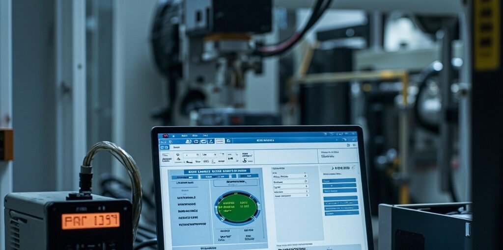
Servo Drive Gain Tuning: A Comprehensive Guide to Optimizing Industrial Motion Control
Introduction
In the realm of industrial automation, achieving precise and efficient motion control is paramount for the smooth operation of machinery in manufacturing, packaging, and assembly lines. Servo drives are the backbone of such systems, providing the necessary control and power to execute complex motion profiles with high accuracy and repeatability. However, the performance of a servo system is heavily dependent on the proper tuning of its control loops. This article delves into the critical aspects of servo drive gain tuning, including the architecture of servo loops, inertia ratio calculation, PI tuning for speed and position loops, mechanical resonance suppression, and feedforward compensation. We will also explore troubleshooting common issues and provide practical insights using real-world products such as the REXROTH HMD01.1N-W0020-A-07-NNNN Servo Drive Control.
Servo Loop Architecture
1.1. The Three Nested Control Loops
A typical servo system employs three nested control loops: the current loop, the speed loop, and the position loop. Each loop operates at a different bandwidth and serves a specific purpose in controlling the motor’s behavior.
1.1.1. Current Loop (Innermost Loop)
- Bandwidth: 1-5 kHz
- Control Method: Fixed by drive firmware based on motor parameters
- Function: Regulates the current supplied to the motor, ensuring that the motor produces the required torque. The current loop is crucial for maintaining precise control over the motor’s output and is typically auto-tuned by the drive during motor commissioning.
1.1.2. Speed Loop (Middle Loop)
- Bandwidth: 50-500 Hz
- Control Method: Adjustable PI (Proportional-Integral) gains
- Function: Controls the motor’s speed by comparing the actual speed with the commanded speed and adjusting the current accordingly. The speed loop is responsible for the dynamic response of the system.
1.1.3. Position Loop (Outermost Loop)
- Bandwidth: 10-300 Hz
- Control Method: Adjustable P (Proportional) gain
- Function: Ensures that the motor reaches the desired position by comparing the actual position with the commanded position and adjusting the speed reference. The position loop is critical for the accuracy of the motion control system.
1.2. Tuning Sequence
The tuning process must be performed from the innermost loop to the outermost loop. This means starting with the current loop, followed by the speed loop, and finally the position loop. This sequential approach ensures that each loop operates correctly before moving on to the next, preventing instability and ensuring optimal performance.
Inertia Ratio Calculation
The inertia ratio is a critical parameter that affects the stability and performance of a servo system. It is defined as the ratio of the load inertia to the motor inertia:
\[ \text{J\_ratio} = \frac{\text{J\_load}}{\text{J\_motor}} \]
2.1. Calculating Load Inertia
- For Rotary Systems:
\[ \text{J\_load} = \frac{\text{m} \times \text{r}^2}{\text{gear\_ratio}^2} \]
where:
- \( \text{m} \) = mass of the load
- \( \text{r} \) = radius of rotation
- \( \text{gear\_ratio} \) = gear ratio of the system
- For Linear Systems:
\[ \text{J\_load} = \frac{\text{m} \times \left( \frac{\text{lead}}{2\pi} \right)^2}{\text{gear\_ratio}^2} \]
where:
- \( \text{lead} \) = lead of the linear motion system (e.g., ball screw)
2.2. Total Motor Inertia
The total motor inertia includes the rotor, encoder, coupling, and gearbox. It is essential to include all components that contribute to the inertia seen by the motor.
2.3. Recommended Inertia Ratios
- General Motion: < 5:1
- High-Precision: < 3:1
- Advanced Tuning: < 10:1 (acceptable with advanced tuning techniques)
A high inertia ratio can lead to oscillation and overshoot, compromising the system’s stability and performance. Therefore, it is crucial to minimize the inertia ratio whenever possible.
Speed Loop PI Tuning
3.1. Initial Gain Calculation
Start with the proportional gain (\( \text{Kp\_speed} \)):
\[ \text{Kp\_speed} = \text{J\_total} \times \omega_c \]
where:
- \( \text{J\_total} \) = total inertia (motor + load)
- \( \omega_c \) = desired crossover frequency (rad/s)
A typical \( \omega_c \) for general motion is \( 2\pi \times 100 \) Hz.
3.2. Integral Gain Calculation
Set the integral gain (\( \text{Ki\_speed} \)):
\[ \text{Ki\_speed} = \frac{\text{Kp\_speed}}{10 \times \text{mechanical\_time\_constant}} \]
3.3. Fine-Tuning
- Increase \( \text{Kp\_speed} \) until oscillation appears.
- Reduce \( \text{Kp\_speed} \) to 60-70% of the critical value to ensure stability.
- Verify the step response:
- Rise time < 5 ms
- Overshoot < 5%
- Settling time < 20 ms
3.4. Load Variation Adjustment
For applications with significant load variations, consider implementing gain scheduling to adjust the gains dynamically.
Position Loop P Tuning
4.1. Proportional Gain Calculation
\[ \text{Kp\_pos} = \frac{\omega_{c\_pos}}{\text{Kv}} \]
where:
- \( \omega_{c\_pos} \) = desired position loop bandwidth
- \( \text{Kv} \) = velocity gain
4.2. Typical Bandwidths
- CNC Machines: 30-100 Hz
- Pick-and-Place Applications: 100-300 Hz
A higher bandwidth results in a faster response but makes the system more sensitive to mechanical resonance.
4.3. Verification
- Following Error: During constant velocity motion, the following error should be less than 10 encoder counts.
- Settling Time: At the target position, the settling time should be less than 10 ms.
Mechanical Resonance Identification and Suppression
5.1. Identification
Use the drive’s auto-tuning function to inject a frequency sweep and identify resonance peaks. Common resonances include:
- Load Coupling: 50-200 Hz
- Belt Drive: 100-500 Hz
- Ball Screw: 200-1000 Hz
- Robot Arm: 10-100 Hz
5.2. Suppression
- Notch Filter: Set the center frequency at the resonance frequency, with a bandwidth of 1-2 octaves and a depth of -20 to -40 dB.
- Adaptive Notch Filter: Some drives, such as the REXROTH HMD01.1N-W0020-A-07-NNNN Servo Drive Control, offer adaptive notch filters that track changes in the resonance frequency.
Feedforward Compensation
6.1. Velocity Feedforward (Kvff)
Reduces the following error during constant velocity motion. Set \( \text{Kvff} = 1.0 \) (100%) for ideal response, and reduce if oscillation occurs.
6.2. Acceleration Feedforward (Kaff)
Reduces the following error during acceleration and deceleration. Set \( \text{Kaff} \) based on the motor torque constant and load inertia. Feedforward does not affect the stability of the system, only the tracking accuracy.
Auto-Tuning Procedures
Most modern servo drives, such as the Hitachi SJ700-075HFEF2 16228514 Frequency Converter, offer one-button auto-tuning. The drive measures the inertia ratio, sets initial gains, and runs a step response test. The auto-tuning result typically achieves 70-80% of the optimal performance, with manual fine-tuning required for high-precision applications. It is essential to save the tuning parameters to non-volatile memory to ensure they are retained after a power cycle.
Troubleshooting Common Issues
8.1. Oscillation at Standstill
- Solution: Reduce the speed loop \( \text{Kp} \), check the encoder mounting.
8.2. Hunting During Motion
- Solution: Increase the position loop damping, check for mechanical backlash.
8.3. Excessive Following Error
- Solution: Increase the position loop gain, verify feedforward settings.
8.4. Motor Overheating
- Solution: Check the current limit, verify the motor-selection match.
8.5. Encoder Fault
- Solution: Check the cable shielding, verify the pulse count per revolution.
FAQ
9.1. What is the recommended inertia ratio for high-precision applications?
The recommended inertia ratio for high-precision applications is less than 3:1. This ensures that the system remains stable and responsive, minimizing overshoot and oscillation.
9.2. How does feedforward compensation affect system stability?
Feedforward compensation does not affect the stability of the system. It only improves the tracking accuracy by reducing the following error during motion.
9.3. What is the purpose of a notch filter in servo tuning?
A notch filter is used to suppress mechanical resonance by attenuating the signal at the resonance frequency. This prevents the resonance from causing instability and oscillation in the system.
9.4. Can I use auto-tuning for all applications?
While auto-tuning is a powerful tool, it may not always achieve the optimal performance required for high-precision applications. Manual fine-tuning is often necessary to fine-tune the gains for specific applications.
9.5. What is the difference between velocity and acceleration feedforward?
Velocity feedforward reduces the following error during constant velocity motion, while acceleration feedforward reduces the following error during acceleration and deceleration. Both are essential for improving the tracking accuracy of the system.
Conclusion
Proper servo drive gain tuning is crucial for achieving optimal performance in industrial motion control applications. By understanding the architecture of the servo loops, calculating the inertia ratio, tuning the speed and position loops, identifying and suppressing mechanical resonance, and applying feedforward compensation, engineers can ensure that their systems operate with high precision and efficiency. Utilizing the advanced features of modern servo drives, such as the REXROTH HMD01.1N-W0020-A-07-NNNN Servo Drive Control, can further enhance the performance and reliability of motion control systems.
Call to Action
Explore our range of high-quality servo drives and components to find the perfect solution for your industrial automation needs. Click on the links below to learn more about our products:
- Rexroth R983038189 ZDR6 DP2-43/75YM for Machine Tools
- Rexroth WE6D62/EG24N9K72L=AN R901235361 4/3 Valve
- Pressure Relief Valve REXROTH SV10 GB1-42 R900453511
For more information, feel free to contact our team of experts.